Authors: Omer Cohen & Raveh Ben Simon
Supervised by: Orr Krupnik
Visit our published materials for this project!
Github
Introduction
Standardized evaluation measures have aided in the progress of machine learning approaches in disciplines such as computer vision and machine translation, and even simulated robotics. However, real-world robotic learning has suffered from a lack of benchmark setups. To tackle this issue, a group of researchers from UC Berkeley developed a unique, cheap, easy to set up, robotic arm environment called REPLAB. The environment is presented as a benchmark for robotic reaching and object manipulation. The details of this environment are laid out in the article:
REPLAB: A Reproducible Low-Cost Arm Benchmark Platform for Robotic Learning Brian Yang , Jesse Zhang , Vitchyr Pong , Sergey Levine , and Dinesh Jayaraman.
Further technical details about how to set up your own REPLAB cell, along with links to the paper and original results, are given on the project website.
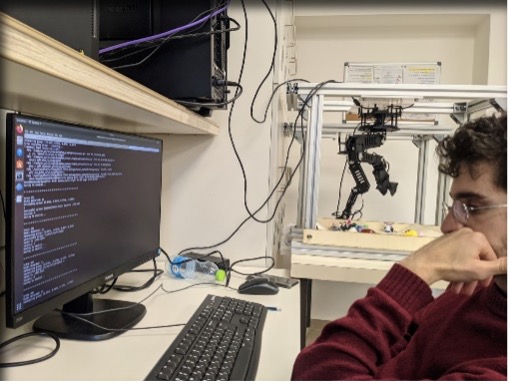
We set out to construct our own REPLAB cell in an attempt to gauge its reproducibility.
Assembly
The robotic arm is a WidowX MK II by Trossen Robotics and can be ordered as a full kit from their website. Apart from the robotic arm itself, the cage and arena need to be built according to the specifications on the REPLAB project website. Access to a laser cutting machine is required, as well as suppliers for some of the aluminum profiles and various bolts. The suppliers listed on the REPLAB project website only ship to the US and Canada; one of our first challenges was to locate similar parts here in Israel.
Building the robotic arm itself was our first major challenge. The instructions given on the Trossen Robotics website were thorough and the assembly of the arm took about 3 days to complete.
We should note that the work was not as smooth as we expected of a robotic kit, as we encountered a lack of some crucial parts:
-
- U2D2 connector to calibrate the servos via a computer.
- Dry TurboFuse glue (which we replaced with a matching Loctite).
- Faulty part missing a bolt hole.
However, upon contacting Trossen Robotics’ support we were swiftly answered and supplied with a suitable U2D2 connector. They also mentioned that the TurboFuse glue was not mandatory for a table-top robotic arm. We dealt with the other issues on our own.
Integration
First, we pulled the Docker image supplied on the REPLAB project website. The original setup required an Intel RealSense SR-300 depth camera, which is part of a discontinued product line. Instead, we used the Intel RealSense D435 depth camera. As we soon learned, the Docker image and code were not compatible with the new camera and thus we began altering the setup and code accordingly.
We are both beginners when it comes to ROS, and thus integrating the new camera to the given environment proved to be hard. Eventually we came across several helpful web sources which we mention in detail in our full technical report.
In general, we found the manual given in the REPLAB GitHub repository was sufficiently detailed and easy to follow, until it came to the camera integration.
In retrospect, we found that there were required code changes which weren’t related to the camera change, which we believe would have resulted in failure to operate a cell even with the SR-300 camera.
All of our changes both to the code and to the Docker image are documented in our Github repository and in the Docker image uploaded to DockerHub (see links above).
Calibration
Calibration of the cell consists of three stages:
-
- Control noise calibration.
- Camera / robot calibration: match the camera coordinate system to the robot frame of reference.
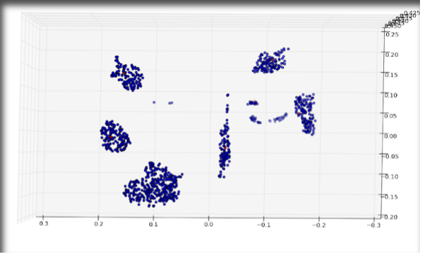
- Point Cloud (PC) base: baseline point cloud image to subtract from point clouds acquired by the depth camera during data collection.
Using the built-in control noise calibration algorithm was simple and we used its results for the entirety of our experiments.
The REPLAB article suggests using a pre-captured reference image to calibrate the camera coordinates to the robot frame of reference. Because we used a different camera, we couldn’t use the preexisting reference image and we had to create one of our own. The manual mentions a calibration routine, but the REPLAB code base does not supply any simple way to achieve it. We Wrote a simple routine to move the arm to pre-programmed spots in the arena with the end effector facing downward. This allows simple generation of a new reference image which corresponds a new camera calibration matrix.
In addition, we noticed that all our grasp attempts did not reach the arena floor. To compensate, we had to tune the Z_OFFSET parameter.
Though not mentioned by the manual, we found that creating a new Point Cloud base image periodically was imperative to the system’s blob detection performance. We recommend recreating the PC base at least once in a workday (or once for every new data collection run).
To test the effectiveness of our calibration, we experimented with the ‘click2control’ GUI provided in the code base and observed sufficiently small margin of error upon moving the arm to a specific location on the arena.
Data Collection
Once the robot passed the calibration tests, we proceeded to perform some data collection.
The REPLAB Docker image includes a data collection algorithm which is quite convenient – we set the arena with various objects and let the robot collect data overnight. To our surprise it worked well, and we came back the next morning to label the grasps.
The code includes an automatic data labeling mechanism which is based on the end effector’s servo value (i.e., whether the gripper is open or closed). We observed that this mechanism performs poorly: it provides false positives and false negatives on many attempts. Instead, we recommend labeling the data manually. The manual data labeling procedure is relatively fast using the supplied tool, and we managed to label around 2,000 grasp attempts in an hour.
The evaluation method, which consists of object grasps and removal from arena, is tedious. The evaluation allows 60 attempts to remove 20 objects from the arena. After every grasp attempt the user must label the attempt as success/failure. This procedure takes about 45 minutes for every evaluation round.
The REPLAB article entails five different grasping algorithms, and thus evaluating every one of them is very time consuming.
We would suggest creating a better (probably image-based) automatic labeling method. This should not pose a grand challenge and would streamline the data collection and evaluation greatly.
Results
We compared and evaluated performance in two ways:
-
- Our environment versus the results reported in the REPLAB article.
- Learning algorithms versus non-learning (heuristic) algorithms.
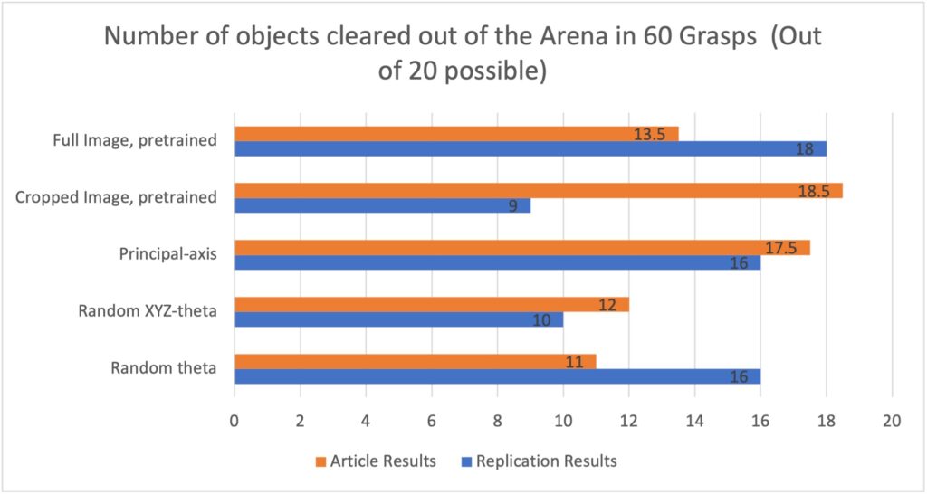
For the learning-based algorithms, we trained the grasp proposal neural networks on the dataset collected for the original REPLAB project, which is supplied on their website. As can be seen in Fig. 1, we were able to achieve performance similar to that reported by the original REPLAB authors, even though our setup is not the one on which the data was collected.
The ‘Fullimage’ method grasped more objects in our setup but ‘Pinto’ (cropped image) grasped less than the result reported in the REPLAB article. Our hypothesis is that the ‘Pinto’ algorithm’s poor performance is linked to the camera replacement. The RealSense D435 camera has higher resolution Than the original SR-300 Camera. ‘Pinto’ uses a cropped image to evaluate the probability of success on a grasp attempt, and the image crop is done with a constant radius of 48 pixels, which was derived specifically for the SR-300 camera. The higher resolution of the D435 causes the crop procedure to yield a smaller field of view around the targeted object. The phenomenon can be seen in Fig. 2:
-
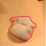
- Figure 2: Comparison of the FOV of cropped image of the same object taken by SR-300 (left) and D435 (right)
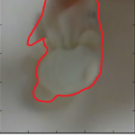
In our input images the object covers a larger part of the image in comparison to the SR-300 input images. We suggest that this phenomenon may cause the poor performance of the algorithm, as the input images fed to the network are inherently different than the ones the network was trained on.
When comparing the non-learning algorithms to the learning ‘Fullimage’, we noticed that ‘Fullimage’ is marginally better than the non-learnings algorithms. This resembles REPLAB’s original results and leads us to the conclusion that the setup was reproduced successfully.
Conclusions
We were able to produce similar results both with heuristic methods and with learning-based methods, even when the latter were trained on data collected in a different environment, with a different camera. Even this mismatched data improved results over the heuristic algorithms, which leads us to believe the REPLAB benchmark is in fact reproducible.
Barring some challenges inherent in working with open-source code and low-cost hardware, we found the process of reproducing the environment easy enough to follow, despite being relatively new to robotics. We are looking forward to experimenting further with the REPLAB cell.